



CRMICRO Primary Agent DC to DC Buck constant current drive IC PT4115EE89E
- Model:
- PT4115EE89E
- Brand:
- CRMICRO
- Batch No:
- PT4115EE89E,50V 1.5A LED恒流驱动,PWM模拟调光驱动IC,CRMICRO华润微,LED驱动芯片
- Desc:
- PT4115EE89E is CRMICRO buck LED constant‑current driver IC, SOT89‑5 package, 6‑50V input, 1.5A max output, supports PWM & analog dimming. GSMicro, authorized CRMICRO distributor, in‑stock, samples & datasheet available
- Stock:
- 300000 PCS
50V/1.5A High‑Brightness LED Constant‑Current Driver PT4115EE89E|CRMICRO Authorized Distributor|GS‑Micro
Keywords: PT4115EE89E | 50V 1.5A LED Constant‑Current Driver | PWM & Analog Dimming Driver IC | CRMICRO
Product Overview: PT4115EE89E is a CRMICRO buck LED constant‑current driver operating in continuous conduction mode. It supports 6‑50V input, max 1.5A output, ±3% output current accuracy, analog / PWM dimming, and comes in SOT89‑5 package. Suitable for automotive lighting, MR16 spotlights, industrial lighting, backlight and emergency lights. As an authorized distributor, GS‑Micro maintains spot inventory and provides samples, datasheets and hardware application reference designs.
PT4115EE89E is a 50V/1.5A buck constant‑current LED driver released by CRMICRO, designed for single or multiple series‑connected high‑power high‑brightness LEDs. It integrates an internal power switch and adopts high‑side current‑sensing architecture with minimal external BOM components. It offers wide 6V~50V input voltage range, up to 1.5A maximum output current, typical ±3% constant‑current accuracy and peak 97% conversion efficiency. The multi‑function DIM pin supports LED on/off control, analog dimming and PWM dimming. Built‑in multi‑level protection features, housed in SOT89‑5 package. It meets mid‑to‑high‑voltage LED driving requirements for MR16 spotlights, automotive LED lights, industrial lighting, emergency lamps, LCD backlight and other applications.
PT4115EE89E sets average LED current via high‑side current‑sense resistor. The DIM pin enables analog dimming and wide‑range PWM dimming. When DIM voltage drops below 0.3V, the internal power switch turns off and the IC enters low‑power standby mode with typical quiescent current of 100μA.
PT4115EE89E is available in SOT89‑5 package, operating temperature ‑40℃~85℃, supplied in tape‑and‑reel packaging of 1000pcs per reel.
⚡ Key Features
Minimum external components to simplify PCB design
Ultra‑wide input voltage range: 6V ~ 50V
Maximum output current: 1.5A
Multi‑function DIM pin: LED on/off, analog dimming, PWM dimming
±3% output current accuracy for excellent brightness consistency
Up to 97% conversion efficiency for low power consumption & energy saving
Constant‑current output configurable by external resistor
Built‑in RCS open‑circuit protection, LED open‑circuit protection, thermal shutdown protection, under‑voltage lockout protection
SOT89‑5 package with thermal pad connected to GND for reduced thermal resistance
Typical Application Scenarios
MR16 spotlights, LED spotlights for halogen lamp replacement
Automotive LED lamps (headlight, taillight, reading light, ambient light)
LED backup lights, fire emergency lighting
LED signal lights, illuminated signs, advertising light boxes
SELV Safety Extra‑Low‑Voltage lighting systems
LCD TV & industrial display LED backlight driving
Ordering Information
| Package | Temperature Range | Orderable Part Number | Packaging | Marking |
| SOT89‑5 | ‑40℃ ~ 85℃ | PT4115EE89E | Tape and Reel 1000pcs/reel | PT4115E xxxxxX |
Key Electrical Parameters
| Parameter Category | Parameter Name | Value | Unit |
|---|---|---|---|
| Input & Output | Recommended Input Voltage | 6~50 | V |
| Input & Output | Maximum Output Current | 1.5 | A |
| Performance | Maximum Conversion Efficiency | 97 | % |
| Performance | Output Current Accuracy | Typ. ±3 | % |
| Performance | Maximum Switching Frequency | 1 | MHz |
| Dimming | Analog Dimming Voltage Range | 0.5~2.5 | V |
| Dimming | PWM Dimming Frequency Range | 0.1~20 | kHz |
| Protection | Thermal Shutdown Trigger Temp. | 155 | ℃ |
| Protection | Under‑Voltage Lockout Threshold | 4.5 | V |
| Operating | Junction Temperature Range | -40~150 | ℃ |
| Standby | Quiescent Current | Typ.60, Max.100 | μA |
Typical Application Schematic

Pin Definition

Operating Principle
PT4115EE89E, together with inductor (L) and current‑sense resistor (RS), forms a self‑oscillating buck LED constant‑current driver working in continuous conduction mode. At VIN power‑up, initial currents of inductor L and sense resistor RS are zero, so does LED output current. The CS comparator outputs high and internal power switch turns on. Current flows from VIN through inductor L, sense resistor RS, LEDs and internal power switch to GND.
Current rising slope is determined by VIN, inductor L and LED forward voltage drop, generating voltage drop VCSN across RS. When (VIN‑VCSN)>230mV, CS comparator output goes low and internal power switch turns off. Inductor freewheeling current flows through L, RS, LEDs and Schottky diode D. When (VIN‑VCSN)<170mV, power switch turns on again. This cycle stabilizes the average LED output current.
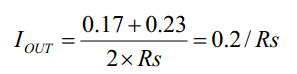
High‑side current‑sensing architecture reduces external component count. With 1% precision sense resistor, LED output‑current accuracy reaches ±3%. Derate thin‑film SMD resistors to 70% of rated power. For 1A output current, two parallel 1206 resistors (0.33Ω and 0.47Ω) are recommended.
The DIM pin supports PWM dimming: output shuts down below 0.3V and runs at full current above 2.5V and ≤5V. Supported PWM dimming frequency:100Hz~20kHz. 0.5V‑2.5V DC voltage enables analog dimming. DIM pin can be left floating. When DIM is pulled below 0.3V, IC enters standby mode with max 100uA quiescent current.
Built‑in TSD thermal shutdown protection triggers at 155℃ and auto‑recovers at 130℃. RCS open‑circuit protection and LED open‑circuit protection enhance system robustness.
Application Notes
Setting Average LED Output Current via External Sense Resistor RS
LED average output current is set by sense resistor RS placed between VIN and CSN: IOUT=0.2/Rs. Condition: DIM pin is floating or DIM voltage>2.5V and ≤5V. RS defines maximum output current; actual output current can be reduced via DIM pin.
Analog Dimming (DC Voltage Dimming)
Apply DC VDIM on DIM pin to lower LED output current; maximum current is defined by RS. LED average‑current formula: IOUT=(0.2×VDIM)/(2.5×RCS).

Full‑scale output IOUT=0.2/Rs is maintained when VDIM ranges 2.5V~5V.
PWM Signal Dimming
Maximum output current is set by RS. Apply variable‑duty‑cycle PWM signal to DIM pin for brightness adjustment. Advantage of PWM dimming: LED chromaticity will not shift. Recommended PWM frequency ≥100Hz to avoid visible flicker, maximum up to 20kHz. When PWM high‑level is 2.5V~5V: IOUT=(0.2×D)/RCS (D=duty cycle).

Shutdown Mode
DIM pin voltage below 0.3V triggers shutdown mode, maximum quiescent current 100μA.
Soft‑Start Mode
Adding capacitor from DIM pin to GND realizes soft‑start by slowly ramping DIM voltage. 0.47µF 0805 ceramic capacitor is recommended. A Schottky diode across capacitor to VIN can accelerate discharge and solve abnormal startup after frequent power cycling.
Freewheeling Diode Selection
Select fast‑recovery Schottky diode with low forward voltage, low parasitic capacitance and low leakage current. Reserve ≥30% margin for current & voltage rating. Pay close attention to reverse leakage at high temperature to avoid extra power dissipation. Low‑Vf Schottky diode is mandatory for AC24V rectification applications.
Input Capacitor Selection
Place low‑ESR bypass capacitor close to VIN pin, which must withstand sufficient RMS ripple current. 50V rated voltage, capacitance ≥22μF, X7R‑grade or higher ceramic capacitor is recommended. Add an extra 0.1µF ceramic capacitor near VIN pin for noise suppression.
Inductor Selection
Recommended switching frequency:100kHz~500kHz, typical value 200KHz; ripple current set to 30% of peak switch current. Inductor saturation current ISAT≥1.3×ILP for 30% design margin. DCR less than 50mΩ is preferred for high efficiency.
Output Capacitor Selection & Output Ripple Reduction
Output capacitor is optional for most applications. To suppress output current ripple, a 2.2μF capacitor in parallel across LED terminals works well; larger value further reduces ripple. Output capacitor does not change operating frequency or efficiency, but affects startup delay and dimming response speed.
PCB Layout & Thermal Guidelines
Place sense resistor RCS close to VIN and CSN pins to minimize sensing error;
Keep power loops (input capacitor, sense resistor, inductor, Schottky diode) as short as possible;
Keep switching‑node traces short and away from IC to reduce radiated interference;
Single‑point grounding for power‑ground and signal‑ground; place 0.1µF ceramic capacitor near VIN;
Connect thermal pad to GND; use large copper pours on PCB, 1oz copper over 25mm² area for better heat dissipation;
Test Considerations
Electronic‑load CV‑mode test may behave abnormally without output capacitor; increase output capacitance to extend startup time;
Use real LED loads for power‑on / power‑off and dynamic‑performance tests;
Frequently Asked Questions FAQ
Q1: How to set the maximum output current of PT4115EE89E?
A: Constant output current is defined by sense resistor RS between VIN‑CSN. Calculation formula Iout=0.2/Rs. 1% precision sense resistor delivers ±3% constant‑current accuracy.
Q2: What dimming modes are supported by DIM pin?
A: DIM pin supports PWM digital dimming and 0.5V‑2.5V analog voltage dimming. IC enters low‑power standby when DIM<0.3V. PWM dimming keeps LED color temperature unchanged, maximum dimming frequency reaches 20kHz.
Q3: What advantages does PT4115EE89E have compared with standard PT4115?
A: Input voltage raised up to 50V, max output 1.5A while conventional PT4115 is mostly 30V/1.2A. Improved ±3% current accuracy and enhanced multi‑level protections, suitable for high‑voltage high‑power LED lighting.
Q4: How to handle thermal shutdown issue on PT4115EE89E?
A: Check input‑to‑output voltage differential; optimize PCB copper pour for thermal dissipation and ensure thermal pad connected to GND; verify saturation current rating of inductor and leakage performance of Schottky diode. Thermal shutdown triggers at 155℃ and auto‑recovers at 130℃.
Q5: Will LED open‑circuit condition damage the chip?
A: The IC integrates LED open‑circuit protection and RCS open‑circuit protection. It enters safe mode under open‑load condition and automatically resumes normal operation after load recovery.
- Grade And Comment
- Question And Answer
- [ Member ] DW***2017-05-27 17:12:10LED汽车灯驱动可以采用PT4115E这一款芯片来设计,PT4115E是输入达到50V DC电压,驱动最大电流1.5A的LED恒流驱动芯片。