DW8534 Non-isolated Buck LED Driver With integrated 500V MOS
DONGWOON-DW8534 Order information
ORDERING PART NUMBER
| MARKING
| PACKAGE
| TRANSPORT MEDIA |
DW8534
| DW8534
xxxxxX
| TO-92 and SOT 23-5
| 3000/Tape and Reel
|
DW8534 Non-isolated Buck LED Driver With integrated 500V MOS General Description:
DW8534 is a non-isolated, constant output current step-down LED driver with 500V MOSFET integrated. Operating in the boundary mode makes it high efficiency and low radiation. Patented algorithms ensure good current accuracy and excellent line/load regulations with lowest BOM cost.
DW8534 is supplied from the MOSFET drain directly, so the auxiliary winding is eliminated, which can light up the LED within 100mS. With unique sampling techniques, DW8534 has multi-protection functions which can largely enhance the safety and reliability of the system, including VDD UVLO, inductor short protection , LED open protection, LED short protection and over-temperature protection.
Non-isolated Buck LED Driver With integrated 500V MOS DW8534 Features:
●Integrated 500V, Low Rds_on MOSFET (30ohm, 100mA maximum output current);
●Excellent line/load regulation;
●Boundary mode operation;
●High efficiency;
●LED OVP and SCP ;
●VDD UVLO;
●Over-temperature protection;
●Brown Out Protection ;
●Inductor short protection ;
●TO-92 and SOT 23-5 package
Non-isolated Buck LED Driver With integrated 500V MOS DW8534 Applications:
●AC/DC LED driver applications
●Signage and decorative LED lighting
●General lighting of flat panel displays
●RGB backlight
●General purpose constant current source
●IBulb light
integrated 500V MOS DW8534 Pin Information
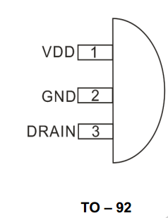
PIN No.(DW8534)
| DW8534 Pin Name | DW8534 Description |
1
| VDD | This pin supplies current to the internal start-up circuitry. This pin must be locally bypassed with a capacitor. |
| 2 | GND |
Chip ground.. |
| 3 | DRAIN |
The drain of MOSFET. |
DW8534 Block Diagram:

DW8534 Typical Application Circuit:

Absolute Maximum Ratings(1)
Symbol
| Parameter
| Ratings
|
DRAIN
| DRAIN Voltage
| 550V
|
VDD
| VDD Voltage
| 5.5V
|
GND
| GND Voltage
| -0.3V ~ 5.5V
|
θJA
| Package Thermal Resistance(2) | 120℃/W
|
θJC | Package Thermal Resistance(2) | 60℃/W
|
TJOPR
| Junction Operating temperature
| -40~+125℃
|
TSTG
| Storage Temperature
| -65 ~ 150 ℃
|
TJ | Junction temperature(3),(4) | 150℃
|
Note (1). Stresses above the max. Valu es listed here may cause permanent damage to the device. Exposure to absolute maximum rating conditions for extended periods may affect device reliability. Maximum ratings are absolute ratings; exceeding only one of these values may cause irreversible damage to the integrated circuit.
2. Measured on JESD51-7, 4-layer PCB.
3. The DW8534 guarantees robust performance from -40°C to 150°C junction temperature. The junction temperature range specification is assured by design, characterization and correlation with statistical process controls.
4. The DW8534 includes thermal protection that is intended to protect the device in overload conditions. Thermal protection is active when junction tempe rature exceeds the maximum operating junction temperature. Continuous operation over the specified absolute maximu m operating junction temperature may damage the device.
Absolute Maximum Ratings
Use of the IC in excess of absolute maximum ratings such as the applied voltage or operating temperature range (TJ) may result in IC damage. Assumptions should not be made regarding the state of the IC (short mode or open mode) when such damage is suffered. The implementation of a physical safety measure such as a fuse should be considered when use of the IC in a special mode when the absolute maximum ratings may be exceeded is anticipated.
DW8534 Recommended Operating Condition
Symbol
| Parameter
| Min.
| Typ.
| Max.
| Unit
|
DRAIN
| DRAIN voltage
|
|
| 500 | V |
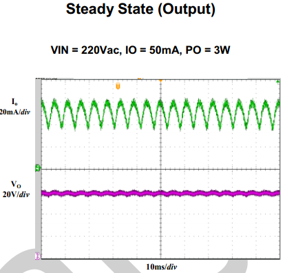
DW8534 Typical Operating Characteristics
(VIN=90VAC~260VAC, Io=50mA, VOUT=60V,or 20LEDs (VF=3V) in series,unless otherwise noted)





DW8534 Detailed Descriptions
The DW8534 is a constant current LE D driver which applies to non-isolation step-down LED system. DW8534 can achieve excellent line and load regulation, high efficiency and low BOM cost wi th few peripheral components.
■Start Up
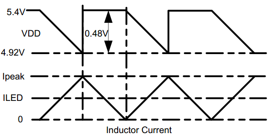
When the internal high voltage start -up circuit charges VDD up to the turn-on threshold, the gate driver starts to switch. In the normal working state, the current source charges VDD to 5.4V when the power MOSFET is off. Once the voltage of VDD is lower than 4.4V, DW8534 stops switching.
■Constant Current Control
DW8534 controls the output current from the information of the current sensing resistor. The output LED average current can be calculated as:
ILED = 0.24 / RCS
Where,
RCS: the sensing resistor connected between chip GND and the VDD capacitor ground.
The inductor current and VDD waveforms are as follows:
■Critical Conduction Mode Operation
DW8534 works in the critical conduction mode of the inductor current. When the external power MOSFET turns on, the inductor current increases from zero linearly. The turn on time of the MOSFET can be calculated
as:

Where,
L : inductance.
ILED : output led current.
VIN : input voltage after rectification and filtering.
VLED : output voltage.
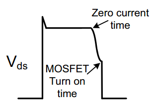
When the power MOSFET turns off, the inductor current decreases. Th e power MOSFET turns on again when
he inductor current is zero. The turn-off time of the MOSFET can be calculated as:
TOFF= 2 ILED *L / VLED
DW8534 works in quasi-resonant mode. When the inductor current decrea ses to zero, resonance takes place between the power inductor, MOSFET output capacitor and stray capacitor. DW8534 can detect the zero-current signals of the inductor, and turn on the MOSFET in the valley, which can reduce the power loss and the EMI radiation. If DW8534 cannot get the zero current signals, the turn off time will be changed to 400uS.
■Over Temperature Protection
When DW8534 temperature is higher than 135°C, LED current reduces, and if it is higher than 150°C, the output current reduces to zero.
■LED Open Protection
When the turn-off time of the MOSFET is less than 5us for 3 consecutive periods, OVP is triggered. Once OVP is triggered, DW8534 keeps off for 800mS. During OVP, DW8534 waits 800mS for the next pulse.
■LED Short Protection
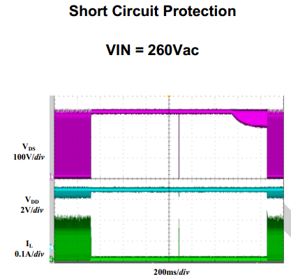
When the output is shorted, DW8534 can¶t get the zero current signals. The turn-off time will be 400uS. If DW8534 cannot detect the zero current signals for 10 consecutive periods, the SCP is triggered, then DW8534 stops switching for 800mS until the next pulse.
■PCB Layout Guidelines
1. The VDD pin must be locally bypassed by a ceramic capacitor.
2. Make the area of the power loop as small as possible in order to reduce the EMI radiation.
3. The chip should be far away from the heating components, such as MOSFET, transformer and diode.
4. Note the chip ground is not connected to the cathode of the input capacitor as usual.
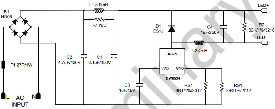
DW8534 Application Reference
VIN: 90VAC ~ 264VAC
VOUT: 40V ~ 60V
IOUT: 50mA
PF: >0.4
Key words of this article:DW8534, Non-Isolated, Buck LED Regulator ,High PFC, High Voltage MOSFET