PT4211BE23E Buck LED Constant‑Current Driver|CRMICRO Authorized Distributor|GS‑Micro
Keywords: PT4211BE23E | PT4211E23E | Buck LED Constant‑Current Driver | CRMICRO | PWM Dimming LED Driver IC
Product Overview: PT4211BE23E / PT4211E23E is a CRMICRO buck constant‑current driver IC in continuous conduction mode. It supports 5‑36V wide input voltage, max 600mA output and PWM pulse dimming, suitable for MR16 lamps, automotive LED lights, LED emergency lamps, LED signal lights and other LED lighting products. GS‑Micro is an authorized distributor with spot inventory and sample requests available.
PT4211BE23E/PT4211E23E is a buck constant‑current source operating in continuous conduction mode, capable of driving single or multiple series‑connected LEDs. Adopting continuous‑conduction‑mode architecture, it delivers high‑efficiency buck constant‑current output, reduces system power consumption and extends LED service life.
Input voltage range: 5V‑36V; output current can be configured via external resistor with maximum 600mA output. It can work with peripheral components for medium‑and‑small‑power LED driving solutions.
The IC integrates internal power switch and adopts high‑side current‑sensing topology to set average LED current. The DIM pin supports wide‑range PWM pulse dimming. When voltage below 0.2V is applied to DIM pin, internal power switch turns off and the IC enters ultra‑low‑current standby state. Built‑in soft thermal protection minimizes LED flicker under high temperature and improves device reliability.
⚡ Key Features
Minimum external components
Wide input voltage: 5V ~ 36V
Up to 93% conversion efficiency
Maximum output current: 600mA
Dedicated DIM pin for wide‑range PWM pulse dimming
±3% output current accuracy
Built‑in LED open‑circuit protection
High‑side current‑sensing architecture
Externally configurable constant‑current output
Soft thermal protection to reduce LED flicker at high temperature
SOT23‑5 package
Typical Application Scenarios
Pinout and Pin Functions
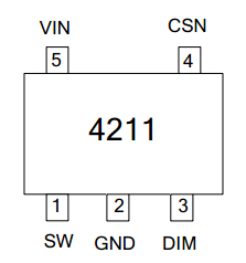
| SOT23‑5 Pin No. | Pin Name | Function Description |
| 1 | VIN | Power supply input pin. Place bypass capacitor close to this pin. |
| 2 | GND | Signal and power ground, connect directly to PCB ground plane. |
| 3 | DIM | PWM dimming input pin; output shuts down below 0.2V and turns on above 1.7V. Floating pin is pulled‑up to 5V by internal 300kΩ resistor. |
| 4 | CSN | Current‑sense terminal. Sense resistor is connected between CSN and VIN to set LED constant‑current output value. |
| 5 | SW | Switch output node, internal power switching pin. |
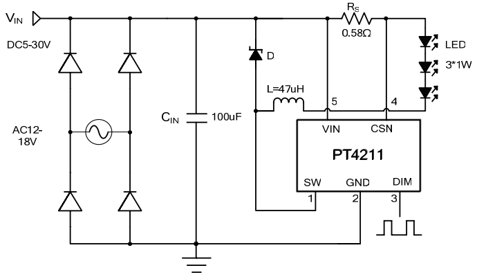
Typical Application Schematic
Ordering Information
Orderable Part Number: PT4211BE23E / PT4211E23E
Package: SOT23‑5
Temperature Range: -40℃ ~ +85℃
Packaging: Tape & Reel, 3000pcs/reel
MOQ: 3k pcs (samples available)
Lead Time: In‑stock / 4 weeks (subject to order quantity)
Frequently Asked Questions FAQ
Q1: How to set output current for PT4211BE23E?
A: The average LED current is set by sense resistor RS connected between VIN and CSN. Formula: IOUT=0.2/Rs. 1% precision sense resistor delivers ±3% constant‑current accuracy.
Q2: What are the requirements for DIM‑pin dimming?
A: DIM pin supports PWM pulse dimming with recommended frequency range from 100Hz to 20kHz. Output shuts down below 0.4V with typical 95uA standby current. DIM pin can be left floating in normal operation and pulled‑up to 5V by internal resistor.
Q3: What is thermal protection logic of PT4211?
A: Soft current‑derating activates when junction temperature exceeds 135°C to suppress temperature rise. Full shutdown triggers at 150°C. The IC resumes operation automatically after temperature drops by 15°C to mitigate LED flicker.
Q4: Will LED open‑circuit condition damage the chip?
A: Built‑in LED open‑circuit protection puts IC into low‑power safe mode under open‑load condition to protect chip and peripheral devices. Normal operation restores after load reconnection.
Q5: What are recommended inductor parameters?
A: Recommended inductance range: 47uH~100uH. Inductor saturation current should reserve 30%‑50% margin above output current. Larger inductance is preferred for better constant‑current performance under high input voltage.
*Parameters are referenced to official CRMICRO datasheet. Actual performance shall refer to the latest official datasheet. GS‑Micro Semiconductor reserves the right of final interpretation.